What's up with this
banner thing?
If
you don't see a navigation bar on the left, CLICK HERE
|
|
|
February
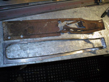
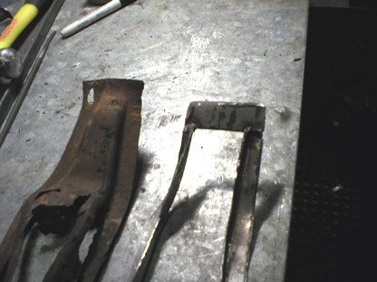
12, 2004 Bracket FabricationI spent the last two nights out in the shop polishing stainless trim, and I'm very pleased with the results. So far I've buffed both door belt moldings, the windshield center post, the trim between the body and the rear splash apron and a few interior items. I figured I didn't need to make another page to show all that because it's basically the same as the February 8 entry. As much as I enjoy buffing (well, enjoy is a strong word), I wanted to make some progress on the car itself, since I can buff trim anytime. In my quest to get the body off the frame, I decided I needed to make repairing the floor a priority. Rebuilding it from the ground up seems to make the most sense, since everything under the floorboards helps to support the floor itself. With that in mind, I decided to find a way to build another support bracket to replace the rusted-out one I removed. I did some reading about forming sheet metal and looked at a few different ways of making this. I could just take some very heavy gauge steel and bend it to the approximate shape of the original and weld it in there. It would certainly be strong enough, but it would look wrong. Then I read a chapter in Ron Fournier's excellent Metal Fabricator's Handbook about hammer forming. That looked like the solution for this problem. Basically, hammer forming is simply building a form and hammering a piece of sheet metal over it until it duplicates the form's shape. Easy. Well, easy when you're working with aluminum or thin steel, as Ron does in his book. Unfortunately, this bracket is made from at least 16-gauge sheet and is a complicated stamping. After making a pretty darned nice plywood buck, I tried hammering a 16-gauge sheet of mild steel over it and had little success. The metal was just too stiff. Then I decided to make the bracket out of two pieces--a perimeter piece to form the surfaces that will be spot-welded to the bottom of the floor and a center piece to give it rigidity. The photos below will make it clearer how I did this. The first thing I did was rough-in the basic shape of the perimeter of the piece and cut out the center. This was done easily with a combination of the cut-off wheel and sawz-all. I made sure to leave enough meat on the perimeter to form the sides of the raised center of the bracket. Then I filed all the edges smooth. Now that I had a basic shape, I proceeded to duplicate the bend in the bracket near the narrow end. The narrow end is welded to the body mount in a near-vertical position, and the bracket curves to meet the floor. The curve is about 45 degrees. I hammered the curve into the blank using a large metal wheel I had lying around from an ancient wheelbarrow. It matched the radius of the original bracket almost perfectly. With the shape close to correct, I
started forming the raised center section. I bought a little anvil and trim hammer from
Eastwood
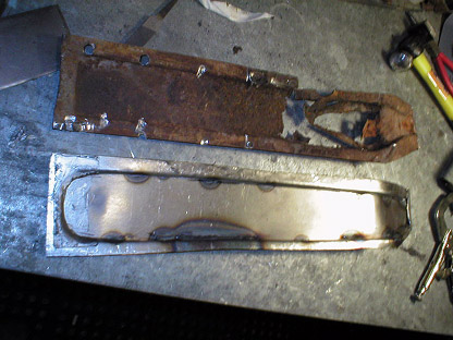
To finish the bracket, I just welded a flat piece of steel to the top of the flange to replicate the basic design of the original. I cut it roughly to size, tacked it in place, marked the edges and made my final cuts. Then I tacked it in place around the perimeter and hammered all the flanges flat and level so it would fit flat on the floorboards.
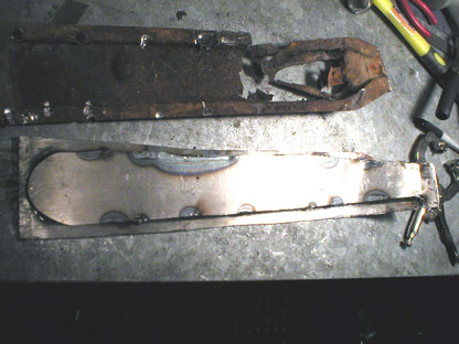
I laid the weld on pretty heavily around the perimeter of the outside, partially for strength, but primarily so I could round the corners off for a more finished appearance and to make it look like the original piece. Unfortunately, the die-grinder bits I had were no match for the steel and wore out pretty quickly. I'm going to pick up a few new carbide-tipped grinding bits this weekend, and I'll finish detailing the piece and show it to you next time. Previous
Restoration Day E-mail me at toolman8@sbcglobal.net This page accessed Thanks, Fidget! |